Flushing block is the normal term for a porous bottom block, through which gas can be introduced into the melt in furnaces or a ladle. The melt is usually flushed with argon. The gas is fed into the melt at low pressure, and removed from the melt by the partial pressure reduction of other gases. The blowing in of flushing gas (including nitrogen) can also be used to stir or mix the melt with added reaction materials, e.g. carburisation and desulphurisation agents.
When melting chrome-nickel alloys in the crucible induction furnace, flushing
with argon can significantly reduce the melting and alloying times.
In the case of light metals and zinc, a higher melting performance can be
achieved with the aid of a nitrogen flushing lance due to the intensive movement
of the bath.
Output is the term used in electrical technology for the product of voltage and current. For direct current, P = U · I applies, with the unit Watt (W).[1] For alternating current, U · I is the apparent power S, with the unit volt-ampere (VA); the active power is P = U · I · cos φ, given in Watts.[2]
References
Herbert H. Netzel: Induktionsofenhandbuch. 3rd edition, Eigenverlag IES, Witten 2003, p. 133.
Maintenance of production plant leads to the improved availability of such systems. On the one hand there is pure repair maintenance, i.e. which is only carried out when the system has broken down or when minor faults provide indications of possible failure. For some components, this can still be the best solution. On the other hand, it is becoming increasingly necessary to undertake repair measures before damage actually occurs. In the case of cars, inspections are carried out and certain parts replaced on the basis of mileage or the time interval between servicing. The same procedure should also be considered for induction furnace systems and the relevant system components, in order to avoid unpleasant surprises. For this reason, some companies have introduced preventive maintenance. Depending on the level of utilisation of systems, maintenance work and checks are carried out with a view toward maintaining availability of the system. Certain parts are replaced as a preventive measure, irrespective of their actual condition, so that unforeseeable or unavoidable breakdowns cannot occur. This can include for example the replacement of an induction furnace coil after 5, or even after 3 years of operation. Depending on the condition of cooling water hose surfaces, it may prove necessary to replace such hoses prematurely even after very short operating times. The firm of ABB introduced a system of preventive maintenance by means of checklists as early as the mid-1970’s. In this process, as for a car undergoing a road test, the whole system and all its components are inspected, from the furnace transformer to the casting spout, and the further procedure or necessary repairs established. Some foundries have these checks carried out every year in the period up to April, so that the necessary measures can be taken during or even before the company holidays.
Coil short-circuit is a short-circuit between 2 parallel windings, which can occur due to an insulation fault. If for example there is too much damp or moisture in the area of the intermediate layers due to inadequate drying, the voltage must be reduced to a low level, so that no leak currents can flow. As a rule, such leak currents are only very low, and this will not lead immediately to short-circuits. In the long term however, a dangerous point will be created, which can be further damaged with every new lining.
If now in the course of the coil’s life, e.g. after 18 months operating time, and under moist weather conditions and formation of condensation on the coil copper, the coil is activated at too high a voltage (> 1,000 V), this can lead to a short-circuit/winding short. The copper of the coil is eroded as in the case of electrode welding, and water can leak out. If the leaking water cannot escape through the intermediate spaces of the coil, the water will penetrate further and further toward the melt, and this will inevitably lead to a water vapour explosion. In order to prevent this, most furnace manufacturers have chosen an open coil construction with water-permeable construction elements. The “packing of the furnace coil” with glass fibre materials and waterproof coatings has in the past often been proven to be an error.
Winding shorts can also occur due to localised over-heating at the inner edges of the intermediate insulation layers. The lightly carburised intermediate layers can retain the moisture very well, thus providing the ideal conditions for a winding short. Accumulations of scrap always occur in the rear area of the furnace coil. This material cannot fall down when the furnace is tipped. Under the effects of the magnetic field, scrap can also collect in the area of the induction coil in the coil jacket, subsequently leading to a winding or earth short. To avoid this, the lower area of the furnace should be cleaned every 4 weeks or vacuumed out with an industrial vacuum cleaner. Under no circumstances should compressed air be used, since this could blow metal parts behind the “core insulation”. This will result in an earth short, which can only be located laboriously by checking every iron pile.
If dark areas can be seen on the inner surface of the furnace coil after removing
the crucible, this area should be carefully cleaned of plaster and the condition of
the intermediate layers checked. This check and any subsequent repair may well
avoid unexpected failure with devastating consequences.
Cooling water is needed to dissipate the heat losses of the furnace coil, caused by the high current and the resistance of the furnace coil, the losses in the iron piles, the short circuit ring and the thermal losses from the crucible wall. The water is usually obtained from the municipal supply system. Only in the case of very hard water with a very high limescale content is it necessary to resort to boiler water or treated water. The water runs within a closed circuit, and only the “lost water” has to be replaced.
Coil grout is applied in crucible induction furnaces direct to the coil, which is insulated with intermediate layers. This ceramic “coil insulation” is also referred to as the smooth coil plastering. This serves to even out any uneven areas of the coil at the inner coil wall, and as a sliding bearing for the crucible, which is gradually increasing in size. Between the coil plastering and the wear crucible, a separating material of micanite, Isoplan or similar materials is applied as an “insulating layer”. The crucible can slide down the wall as the wall gets colder and upwards as it heats up. If a crucible is operated continuously without any “extended interruptions”, this sliding or separating layer can be dispensed with. In the case of a 3-t furnace and 10 crucible changes per year, this can provide a saving of approx. 1,500 €, or for 20-t furnaces of approx. 5,000 €.
Making up the charge is the compiling and calculating of the charge by type and quantity, so that the melt reaches the required chemical composition. The result is recorded in the charge list. The subsequent filling of the charging device is called charging.
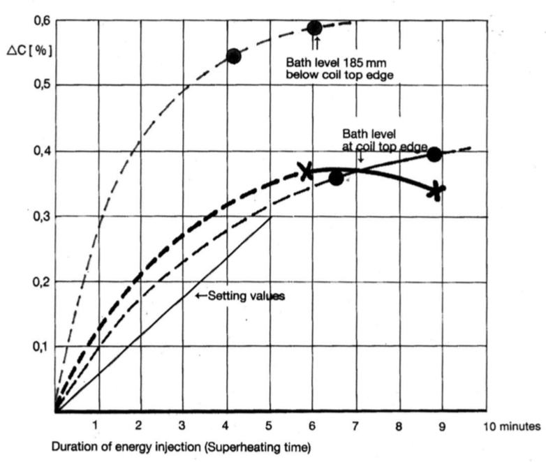
Carbonisation is essential in the production of cast iron from steel scrap and carbon, since the exact carbon content is very rarely achieved with the metallurgical sample. As a rule, the carbon content must be increased by up to 0.3%.
The induction crucible furnace is very well suited for the carbonisation process. The bath movement, agitating effect and the simultaneous temperature increase produce the optimum results, provided that the following conditions are also observed. For 0.3% carbonisation, these are 5 minutes agitation time, a temperature increase of 100 K and a bath filling level above the active induction coil of approx. 25% of the coil height for mains frequency (50/60 Hz), and about 5% of the coil height for medium frequency (500 Hz) with the same specific performance. The specific performance for equal bath movement is approx. 240 kW/t for mains frequency, 545 kW/t at 250 Hz and 750 kW/t at 500 Hz.[1]
If in certain cases carbonisation by approx. 0.5% is required, an agitation time of approx. 7 minutes must be provided, in addition to increasing the temperature differential from 100 K to 130 K, in order to achieve reliable dissolution of the carbon in the melt.
For the 3 frequencies specified above, the following furnace sizes and performances can be regarded as ideal:
NF-50/60Hz
12.5t – 3,000kW
9 minutes
for 100 K – 25% over-filling
MF-250Hz
5.5t-3,000kW
4 minutes
for 100 K – 25% over-filling
with 2,400kW
5 minutes
for 100 K – 20% over-filling
with 3,000kW
5 minutes
for 125 K – 25% over-filling
MF-500Hz
4.0t-3,000kW
3 minutes
for 100 K – 25% over-filling
with 1,800kW
5 minutes
for 100 K – 15% over-filling
with 3,000kW
5 minutes
for 166 K – 25% over-filling
From these figures, it can be seen that a mains frequency furnace can be overfilled by approx. 300 mm, a 250 Hz furnace by approx. 220 mm and a 500 Hz furnace with suitable performance by approx. 150 mm. If a significantly higher specific performance is installed, due to the melting performance per hour required for operation, the metallurgical melting control must be properly set, and when reaching the upper edge of the coil, the required quantity of carbon for the final filling level must be added.
For example, a 5.5 t furnace operating at 4,800 kW has a superheating capacity
of 40 K/minute, and thus an agitating time of approx. 2.5 minutes for 100 K. In
order to maintain the agitating time of 5 minutes, the temperature difference
would have to be 200 K. This value is not realistic in practice. This furnace
should be operated at approx. 3,000 kW for about 5 minutes with a temperature
difference of 125 K.
movement force, which in an induction crucible furnace acts vertically to the
wall, and thus pushes the melt away from the crucible wall. The melt can only
compensate for this force in an upward direction, and this creates the bath cone,
which is higher or lower depending on the performance and frequency.
Amount and direction of the melt flow in a 6 t coreless furnaceCarburization velocities in a 6 t induction furnaceTest data for establishing the carburising speedMelt flow in a coreless induction furnace ITMK 6
References
Herbert H. Netzel: Induktionsofenhandbuch. 3rd edition, Eigenverlag IES, Witten 2003, p. 178. Empirical value, not a manufacturer specification. Elsewhere in the same handbook (p. 19) the same comparison is given as 300 kW/t. We follow the majority of the mentions in our own corpus.