
Melting Heat

Melting heat, also called latent heat of fusion, is the thermal energy a metal absorbs to change from solid to liquid at its melting point, without any further rise in temperature. It is a physical constant, for example about 247 kJ/kg for iron, 397 kJ/kg for aluminum and 205 kJ/kg for copper, and matters for sizing furnace energy demand.

Melting Heat Versus Sensible Heat

Melting a piece of cold metal takes three separate amounts of energy: sensible heat to warm the solid up to its melting point, latent heat (the melting heat) to convert it from solid to liquid at that fixed temperature, and further sensible heat to superheat the liquid above the melting point for pouring. The melting heat is the step where temperature does not rise even though energy keeps going in, because the energy is used to break the solid’s atomic bonds rather than to speed up atomic motion.

Typical Values for Foundry Metals

Melting heat is a physical constant of each element, not a specification value, so it is quoted in materials handbooks rather than in a DIN standard. Published values vary somewhat between sources, generally within about ten percent, which is normal for this kind of thermophysical data.

MetalMelting Point (approx.)Melting Heat (approx.)
Iron1538°C247 kJ/kg
Aluminum660°C397 kJ/kg
Copper1085°C205 kJ/kg

Practical Relevance: Furnace Energy Demand

Melting heat is one of the figures a foundry needs to size furnace energy demand, alongside sensible heat and superheat. Aluminum illustrates why melting point alone is misleading: at 660°C it melts far below iron, yet its melting heat per kilogram is higher than that of iron or copper, which is one reason melting and remelting aluminum is comparatively energy-intensive for the tonnage produced. Alloys behave differently from pure metals here, because they generally solidify over a temperature range instead of at one fixed point, so a single melting-heat figure for an alloy such as cast iron is an approximation rather than a defined constant, the same way its eutectic temperature only applies exactly at one specific composition.

Frequently Asked Questions About Melting Heat

Is melting heat the same as melting point?

No. The melting point is a temperature. Melting heat is an amount of energy, usually given in kJ/kg or kJ/mol, needed at that temperature to complete the change from solid to liquid.

Why does aluminum need so much energy to melt despite its low melting point?

Because its melting heat per kilogram is comparatively high, around 397 kJ/kg, higher than iron or copper. Melting point and melting heat are independent figures, and a low melting point does not guarantee a low energy demand.

Does alloying change the melting heat?

Yes, and it also changes how cleanly the concept applies. Alloys typically solidify over a temperature interval rather than at a single point, so their effective melting heat is spread across that interval instead of released at one fixed temperature, unlike a pure metal or a composition at the eutectic point.

Standard Reference

No DIN standard defines melting heat; it is a tabulated physical property, not a specification figure.

Further Terms

  • Arc furnace – where melting heat feeds directly into energy demand calculations
  • Eutectic temperature – the one alloy composition that melts at a single fixed point, like a pure metal
  • Alloy – composition changes both the melting range and the effective melting heat
Flowability

Flowability, also called fluidity, describes the ability of liquid metal to flow through a mold cavity and fill thin sections before it solidifies. It depends on viscosity and freezing behavior: a narrow freezing range, as at the eutectic temperature, keeps the liquid channel open longer than a wide range, since no mushy two-phase zone blocks the flow front.

What Determines Flowability

Flowability is not the same as viscosity alone. It also depends on how the alloy solidifies: a narrow freezing range, as at the eutectic temperature, keeps the liquid channel open longer than a wide pasty range does, because there is no mushy two-phase zone to block the flow front early. Superheat above the liquidus temperature, oxide film formation on the melt surface, and the wall thickness of the mold cavity all add to or work against fluidity as well.

Measuring Flowability: the Spiral Test

The most common shop-floor method is the spiral fluidity test: molten metal is poured into a narrow spiral-shaped channel mold, and the length the metal reaches before it solidifies and stops flowing becomes the fluidity index. A longer spiral casting means higher flowability under the test conditions used. The method goes back to the early 20th century and has been adapted with many spiral geometries since; there is no single DIN standard that fixes one universal spiral shape or test procedure.

Flowability in Foundry Practice

Good flowability is what lets a foundry cast thin walls, fine detail, and long thin-walled sections without cold shuts or incomplete fill. This is one practical reason alloys are often kept close to the eutectic composition. The term also appears in a second, unrelated sense on the molding side: the flowability of the molding sand itself, meaning how freely the sand packs around the pattern during sand preparation. Both senses use the same word but describe different materials in the process.

Factors Affecting Metal Flowability

FactorEffect on Flowability
Superheat above liquidusHigher superheat generally improves flowability
Freezing rangeNarrower range (eutectic alloys) improves flowability
Oxide film / surface tensionStronger film reduces flowability
Mold wall thicknessThinner walls reduce achievable flow length

Frequently Asked Questions About Flowability

Is flowability the same as viscosity?

No. Viscosity is one input to flowability, but freezing behavior matters just as much. Two alloys with similar viscosity can show different flowability if one solidifies over a wide pasty range and the other solidifies close to a single point.

Why do eutectic alloys generally have better flowability?

A eutectic alloy solidifies at one fixed temperature instead of over a range, so it stays fully liquid right up to the point of solidification, without an intermediate mushy zone slowing the flow front.

Can flowability be checked without lab equipment?

Yes. A spiral test casting is a simple, practical shop-floor check: pour the spiral mold under normal casting conditions and measure how far the metal ran before it stopped.

Standard Reference

No DIN standard was found that fixes a single spiral fluidity test procedure or geometry; foundries and test laboratories use their own established spiral molds.

Further Terms

  • Eutectic temperature – the composition and temperature that give the narrowest freezing range
  • Sand preparation – where the unrelated meaning, mold sand flowability, applies
  • Alloy – composition choice is one of the main levers over flowability

Eutectic Temperature

The eutectic temperature is the single, fixed temperature at which a liquid alloy of a specific composition solidifies directly into a solid mixture, without a pasty two-phase range. In the iron-carbon system this occurs at about 4.3% carbon: around 1153°C in the stable system, where carbon separates as graphite, or 1147°C in the metastable system, which forms ledeburite.

The Eutectic Point in the Iron-Carbon System

In the iron-carbon system, the eutectic reaction takes place at a carbon content of roughly 4.3%. Two versions of the diagram give slightly different values: the stable system, where carbon separates as graphite, places the eutectic at about 1153°C; the metastable system, where carbon stays bound as cementite and forms ledeburite, places it at about 1147°C. Both numbers describe the same alloy family, cast iron, just under different cooling conditions.

Why the Eutectic Point Matters in Foundry Practice

Foundries design cast iron close to the eutectic composition because it gives the lowest possible melting and pouring temperature for the whole iron-carbon series. A melt at or near the eutectic point also solidifies over a very narrow temperature interval instead of a wide pasty range, which keeps the liquid channel open longer while filling the mold. That is one reason eutectic and near-eutectic cast irons show better mold-filling behavior than alloys further from the eutectic composition. Compositions with less carbon than the eutectic point are called hypoeutectic and form primary austenite dendrites on cooling; compositions with more carbon are hypereutectic and form primary graphite before the eutectic reaction sets in.

Stable and Metastable Eutectic Compared

SystemApprox. Carbon ContentApprox. Eutectic TemperatureSolid Product
Stable (graphite)4.26% C1153°CAustenite + graphite
Metastable (cementite)4.3% C1147°CLedeburite (austenite + cementite)

Frequently Asked Questions About Eutectic Temperature

What is the difference between the eutectic point and the eutectic temperature?

The eutectic point is the combination of composition and temperature at which the eutectic reaction occurs. The eutectic temperature is just the temperature value of that point, always paired with a specific composition.

Is eutectic cast iron the strongest cast iron?

No. Eutectic composition gives the best castability and fluidity, not the highest strength. Hypoeutectic irons with more primary austenite often reach higher mechanical properties, at the cost of a higher melting and pouring temperature.

Why does an alloy at the eutectic composition melt at a lower temperature than either pure component?

In a eutectic system, mixing two components lowers the freezing point of the mixture below that of either pure substance. The eutectic composition is the single mixing ratio where this depression reaches its minimum for the system, which is why it marks the lowest point on the phase diagram. Not every alloy system has a eutectic point: systems with complete solid solubility, such as copper-nickel, have no eutectic and solidify over a temperature range between the melting points of the pure components.

Standard Reference

No DIN standard sets the eutectic point itself; it is a materials-science constant of the iron-carbon system, not a specification value. DIN EN 1561:2024-03 (grey cast iron) and DIN EN 1563 (ductile cast iron) build on it indirectly, because both standards classify iron grades that foundries keep close to the eutectic carbon content for castability.

Further Terms

  • Cementite – the hard phase that forms at the metastable eutectic point
  • Vermicular graphite – a graphite morphology shaped by cooling conditions near the eutectic point
  • Flowability – benefits directly from the narrow freezing range at the eutectic composition
  • Curie point – another fixed-temperature transformation point, but magnetic rather than a phase change of state

Dye Penetrant Inspection

Dye penetrant inspection, also known as penetrant testing, is a non-destructive method used in materials science to detect surface cracks and pores in castings or other workpieces. A coloured penetrant is applied to the cleaned surface, seeps into any cracks by capillary action, and is then drawn back out by a developer, making even the smallest surface flaws visible.

What is dye penetrant inspection and how does it work?

Dye penetrant inspection, often referred to as “Penetrant Testing (PT)”, is an easy-to-perform method of materials testing that is particularly widespread in the foundry industry. First, the surface to be tested is thoroughly cleaned to remove dirt or foreign particles. A coloured test medium, the so-called penetrant, is then applied; due to its low surface tension, it penetrates deep into any existing cracks or pores. The excess penetrant is then carefully removed, and finally a developer is applied. The developer draws the penetrant out of the flawed areas, making cracks clearly visible.

Applications of dye penetrant inspection in the foundry industry

In the foundry industry, dye penetrant inspection is used above all for quality control of castings such as steel, aluminium or cast iron components. It is particularly well suited to testing complex-shaped components or parts that are exposed to high mechanical loads. This simple test method allows surface quality to be assessed quickly and cost-effectively. Typical application examples include parts from the automotive industry, aircraft components, and machinery and plant components.

Advantages and limitations of dye penetrant inspection

The major advantages of dye penetrant inspection include its simple handling, low-cost application and the fast availability of test results. In addition, even the smallest cracks can be reliably detected. However, this method cannot provide any information about defects inside the material, as it is limited exclusively to surface testing. For deeper material examinations, complementary methods such as ultrasonic testing or X-ray inspection are required.

Process steps at a glance

StepDescription
1. CleaningThe surface to be tested is thoroughly cleaned to remove dirt or foreign particles.
2. Penetrant applicationA coloured penetrant with low surface tension is applied and penetrates deep into cracks or pores.
3. Excess removalThe excess penetrant is carefully removed from the surface.
4. Developer applicationA developer is applied, drawing the penetrant back out of flawed areas.
5. InspectionCracks and pores become clearly visible for evaluation.

Related standards

Dye penetrant inspection is commonly carried out in accordance with recognised standards such as ISO 3452 (Non-destructive testing – Penetrant testing) and ASTM E165 (Standard Practice for Liquid Penetrant Testing).

Frequently asked questions

What does dye penetrant inspection detect?

Dye penetrant inspection detects surface cracks and pores in castings or other workpieces, including even very small cracks.

Can dye penetrant inspection find internal defects?

No. Dye penetrant inspection is limited to surface testing and cannot provide any information about defects inside the material. Deeper material examinations require complementary methods such as ultrasonic testing or X-ray inspection.

What materials can be tested with dye penetrant inspection?

The method is used for quality control of castings such as steel, aluminium or cast iron components, including complex-shaped parts and components exposed to high mechanical loads, for example in the automotive industry, aircraft construction, and machinery and plant engineering.

Ferrite

Ferrite – Basic Properties and Significance in Metallurgy

Definition and Classification

Ferrite is a crystalline phase in the microstructure of iron and steel, consisting of a body-centered cubic (BCC) arrangement of iron atoms. As a pure substance, ferrite is also referred to as alpha iron (α-iron) and forms one of the fundamental structures responsible for the diverse properties of iron-based materials. The name is derived from the Latin word „ferrum“ (iron).

Chemical Composition and Crystal Structure

Ferrite consists mainly of iron with a small proportion of dissolved carbon. The maximum solubility of carbon in ferrite is:

  • At room temperature: approx. 0.008%[2]
  • At 723°C (eutectoid temperature): approx. 0.02%[2]

The body-centered cubic (BCC) crystal structure of ferrite differs fundamentally from the face-centered cubic (FCC) structure of austenite and is responsible for its specific properties, such as higher toughness and lower strength compared to other iron phases.

Formation and Occurrence

Ferrite forms in the iron-carbon system under the following conditions:

  • When pure iron cools from the melt below 1538°C[3]
  • During the eutectoid transformation of austenite below the A1 temperature (723°C)[2]
  • Through precipitation from austenite during cooling between the A3 and A1 temperatures

In the steel microstructure, ferrite occurs in various morphologies:

  • As primary ferrite in hypoeutectoid steels
  • As a constituent of pearlite in the form of ferrite lamellae
  • As Widmanstätten ferrite in the form of needle-shaped structures
  • As granular ferrite after special heat treatments

Physical and Mechanical Properties

Ferrite exhibits the following characteristic properties:

  • High electrical conductivity
  • Ferromagnetism below the Curie temperature (770°C, 1043 K)[1]
  • Relative softness and high toughness
  • Good formability
  • High thermal conductivity

These properties make ferrite an important microstructural constituent for numerous technical applications, especially where ductility and toughness are required.

Ferrite in Different Steel Grades

The ferrite content largely determines the properties of various steel grades:

  1. Ferritic steels:
    • Contain predominantly ferrite in the microstructure
    • Typically chromium-alloyed steels, e.g. grade 1.4016 (X6Cr17) with 16-18% chromium[4]
    • Characterized by good corrosion resistance and moderate strength
  2. Ferritic-pearlitic steels:
    • Contain both ferrite and pearlite
    • Offer a balanced combination of strength and toughness
    • Widely used as structural steels and low-alloy steels
    • Examples: S235JR, C45
  3. Dual-phase steels:
    • Consist of ferrite and martensite
    • Combine good formability with high strength
    • Are frequently used in the automotive industry

Influence of Alloying Elements on Ferrite

Various alloying elements influence the formation and properties of ferrite:

  • Ferrite formers: Chromium, silicon, molybdenum, titanium and niobium widen the ferrite field and promote ferrite formation
  • Austenite formers: Carbon, nitrogen, nickel and manganese narrow the ferrite field and favor austenite formation

Targeted alloying can modify the properties of ferrite, leading to improvements in strength, corrosion resistance or other functional properties.

Heat Treatment and Microstructure Control

Various heat treatment processes can be used to control the ferrite content in the steel microstructure:

  • Ferritizing: heat treatment to increase the ferrite content
  • Coarse grain annealing: leads to a coarsening of the ferritic microstructure and improves machinability
  • Normalizing: produces a fine-grained ferritic-pearlitic microstructure
  • Recrystallization annealing: forms new, strain-free ferrite grains after cold forming

Importance in Foundry Technology

Ferrite plays an important role in cast materials:

  • Nodular graphite iron (GJS):
    • Ferritic GJS offers high elongation and good toughness
    • Pearlitic-ferritic GJS combines higher strength with moderate toughness
  • Grey cast iron (GJL):
    • The ferrite content influences machinability and mechanical properties
    • Ferritic GJL shows improved damping properties

Modern Applications and Research

Research into ferritic steels and their applications continues to evolve:

  • Development of high-strength ferritic steels for lightweight construction
  • Improving corrosion resistance for applications in aggressive environments
  • Optimizing magnetic properties for electrical engineering applications
  • Use in nanostructured materials with improved properties

Testing and Analysis

Various methods are used to determine the ferrite content and microstructure:

  • Metallographic examinations using light microscopy after suitable etching
  • Electron microscopy methods for detailed microstructure analysis
  • Magnetic measurement methods for non-destructive determination of the ferrite content
  • X-ray diffraction and spectroscopic analysis methods

Summary

Ferrite is a fundamental microstructural constituent in iron-based materials, and its characteristic crystal structure and properties largely determine the behavior of steels and cast iron. By specifically controlling the ferrite content and its morphology, material properties such as strength, toughness, corrosion resistance and magnetic behavior can be precisely adjusted. This makes ferrite a key element in modern materials engineering, with applications ranging from automotive engineering to electrical engineering.

Frequently Asked Questions

What is the maximum carbon solubility in ferrite?

At room temperature, ferrite can dissolve a maximum of approx. 0.008% carbon. At the eutectoid temperature of 723°C, this maximum solubility rises to approx. 0.02%.

What is the difference between ferrite and austenite?

Ferrite has a body-centered cubic (BCC) crystal structure and forms below the A1 temperature (723°C), which gives it higher toughness and lower strength compared to other iron phases. Austenite, by contrast, has a face-centered cubic (FCC) structure and occurs at higher temperatures.

Why is ferritic ductile iron tougher than pearlitic ductile iron?

Ferritic nodular graphite iron (GJS) has a matrix consisting mainly of the relatively soft, tough ferrite phase, and it offers high elongation and good toughness. Pearlitic-ferritic GJS contains a higher share of pearlite alongside the ferrite, which combines higher strength with only moderate toughness.

Sources

  1. Kittel, C.: Introduction to Solid State Physics. 8th edition, John Wiley & Sons, 2005, Chapter 12 “Ferromagnetism and Antiferromagnetism”, p. 329, Table 1 “Ferromagnetic crystals” (iron 1043 K). Retrieved 26 Aug 2026.
  2. Eisen-Kohlenstoff-Diagramm. maschinenbau-wissen.de, section on carbon solubility in ferrite, eutectoid temperature 723 °C. Retrieved 27 Aug 2026.
  3. Delta-Eisen. Gießerei-Lexikon, melting point of pure iron 1538 °C. Retrieved 27 Aug 2026.
  4. Kloeckner Metals Germany: Material number 1.4016 (X6Cr17). Material data sheet, chromium content 16.0–18.0%. Retrieved 27 Aug 2026.

Cementite (Iron Carbide)

Cementite, also known as iron carbide, is a hard, brittle interstitial compound of iron and carbon (Fe3C) with an orthorhombic crystal structure and a carbon content of 6.67%. It is a component of many steel grades, typically found as lamellae within pearlite, and has a major influence on hardness and strength, though too much worsens machinability.

Properties and Structure of Cementite

Cementite (Fe3C) is a chemical compound of iron and carbon. This interstitial compound has an orthorhombic crystal structure and is relatively hard and brittle. In the iron-carbon alloy, cementite is a key factor in increasing the hardness and strength of steel.

Role of Cementite in Steel Production

In steel production, cementite is essential for achieving the desired mechanical properties. By controlling the proportion of cementite in the alloy, the hardness, wear resistance, and strength of the final product can be adjusted. Cementite is typically found in the form of lamellae within the pearlite of steel’s microstructure.

Influence of Cementite on Material Processing

Due to its hard nature, cementite has a significant influence on the processing of steel products. While it increases strength and wear resistance, it can also negatively affect machinability, as it makes the material more brittle and can lead to increased tool wear.

In Practice: What Foundry Technicians Need Cementite For

For the foundry technician, cementite is above all a warning sign when it appears where it doesn’t belong. In gray cast iron with lamellar graphite, the cooling rate in the thin-walled sections of the mold determines whether the carbon precipitates as soft graphite or remains bound as hard, brittle cementite. If a thin rib cools too quickly, a “white structure” forms there, meaning free cementite instead of graphite, and this exact spot can then hardly be machined afterward, because the tool wears prematurely on the hard cementite. In practice, wall thickness distribution and melt inoculation are therefore controlled so that cementite only forms where it is desired, for example in the hard surface layer of chilled-iron rolls. In malleable cast iron, cementite is actually the intended starting condition, which is then specifically converted into temper carbon through the annealing treatment.

Cementite Compared to Other Microstructure Constituents

Microstructure ConstituentCarbon ContentHardness (approx.)Character
Ferrite~0.02% C~80–100 HVsoft, ductile
Pearlite~0.8% C (average of ferrite/cementite)~200–250 HVlamellar structure of ferrite and cementite
Cementite (Fe₃C)6.67% C~800–1000 HVvery hard, brittle

Frequently Asked Questions About Cementite

Is cementite an element or a compound?

Cementite is an interstitial compound of iron and carbon with the formula Fe₃C, not an alloy in the strict sense and not a pure element.

Why is cementite so hard?

The orthorhombic crystal structure of Fe₃C offers dislocations hardly any slip planes through which the material could deform plastically. This makes cementite hard, but at the same time brittle.

What is the difference between cementite and carbide?

Cementite is a specific carbide, namely iron carbide, Fe₃C. The term carbide generally covers all compounds of carbon with metals, such as chromium carbide or tungsten carbide.

Standard Reference

DIN EN 1561:2024-03 for gray cast iron with lamellar graphite limits the permissible proportion of free cementite (“white structure”) as a casting defect, because it impairs the machinability and mechanical properties of the component.

Further Terms

  • Carbide – general term for carbon-metal compounds
  • Gray cast iron – cast iron in which cementite is avoided as a casting defect
  • Malleable cast iron – makes deliberate use of cementite conversion
  • Martensite – contains carbon trapped in solid solution rather than precipitated cementite

Non-ferrous metals

Non-ferrous metals are metals and alloys that either contain no iron at all or contain iron only in trace amounts, for example aluminium, copper, zinc, tin, lead and nickel. Light metals such as aluminium and magnesium have markedly lower densities than iron and steel, while others, such as copper, nickel and lead, are as dense as or denser than steel.

What Are Non-Ferrous Metals and Their Properties?

Non-ferrous metals comprise a wide variety of different materials, including aluminium, copper, zinc, tin, lead, nickel and their alloys. Unlike iron and steel, some non-ferrous metals, most notably the light metals aluminium and magnesium, have markedly lower densities; others, such as copper, nickel and lead, are as dense as or denser than iron and steel. As a group, non-ferrous metals typically offer excellent electrical and thermal conductivity and good corrosion resistance. These properties make them ideal for applications where weight savings and resistance to environmental influences are decisive, such as in the automotive industry, electrical engineering and construction.

Applications and Examples of Non-Ferrous Metals

Aluminium, for example, is widely used in vehicle and aircraft construction as well as in the production of packaging, since it is light, robust and corrosion-resistant. Copper is found in electrical cables, pipelines and electronic components, thanks to its excellent electrical and thermal conductivity. Brass and bronze, two copper alloys, are often used for jewellery, art objects and technical applications. Zinc is mainly used for corrosion-protection coatings and alloys, an area also covered in our overview of the zinc vapour process, while nickel and its alloys are used in applications that require particular corrosion resistance or heat resistance.

Importance of Non-Ferrous Metals in the Foundry Industry

Non-ferrous metals play a central role in foundry technology, as they make it possible to manufacture complex-shaped, often highly application-specific components. Precision casting or die casting of aluminium, for instance, enables particularly fine and detailed structures while still achieving high strength and low weight. Non-ferrous metal castings are also characterised by good mechanical workability and surface quality, which makes further processing and integration into different products easier. Their flexibility and wide range of applications make non-ferrous metals indispensable in modern manufacturing technology.

Non-Ferrous Metals at a Glance

MetalKey property / application (per source)
AluminiumLight, robust, corrosion-resistant; used in vehicle and aircraft construction and in packaging; enables fine, detailed structures in precision casting or die casting
CopperExcellent electrical and thermal conductivity; used in electrical cables, pipelines and electronic components
Brass / Bronze (copper alloys)Used for jewellery, art objects and technical applications
ZincUsed for corrosion-protection coatings and alloys
TinGood electrical/thermal conductivity, good corrosion resistance
LeadGood electrical/thermal conductivity, good corrosion resistance; denser than iron and steel, not lower
Nickel (and alloys)Used in applications requiring particular corrosion resistance or heat resistance

Frequently Asked Questions About Non-Ferrous Metals

What counts as a non-ferrous metal?

Non-ferrous metals are metals and alloys that contain no iron, or contain iron only in trace amounts. Typical examples are aluminium, copper, zinc, tin, lead, nickel and their alloys, including brass and bronze.

Why are non-ferrous metals used in the automotive industry?

Density varies widely among non-ferrous metals: light metals such as aluminium and magnesium are markedly lower in density than iron and steel, while others, such as copper, nickel and lead, are as dense as or denser than iron and steel. Combined with good electrical and thermal conductivity and good corrosion resistance, the light non-ferrous metals in particular are valuable wherever weight savings and resistance to environmental influences matter, which is why non-ferrous metals are used in the automotive industry, electrical engineering and construction.

What role do non-ferrous metals play in foundry casting?

In foundry technology, non-ferrous metals make it possible to produce complex, application-specific components. Precision casting or die casting of aluminium, for example, allows fine, detailed structures with high strength and low weight, and non-ferrous metal castings offer good mechanical workability and surface quality that simplify further processing.

Tensile Strength and Hardness: Conversion Approaches and Practical Solutions

Tensile Strength and Hardness: Conversion Approaches and Practical Solutions

Tensile strength (Rm) is the maximum tensile stress a material withstands before fracture, given in N/mm². For grey cast iron (GJL), it ranges under DIN EN 1561 from 100 N/mm² (EN-GJL-100) to 350 N/mm² (EN-GJL-350); for ductile iron (GJS), it ranges under DIN EN 1563 from 350 N/mm² (EN-GJS-350-22) to 900 N/mm² (EN-GJS-900-2).[3] The figure in the grade name is the minimum tensile strength for separately cast test samples. No reliable formula converts hardness to tensile strength for either material.

Basics of the Relationship Between Hardness and Tensile Strength

Between tensile strength (Rm) and hardness measurements there is an empirical relationship. Both properties depend on the microstructure of the material. For grey cast iron and ductile iron, this has not produced a reliable formula; the standard grade tables below take its place.

Hardness Ranges by Cast Material per Mill Standard

Grey Cast Iron / Lamellar Graphite Iron (GJL)

A conversion formula from hardness to tensile strength is not reliable for GJL. Hardness ranges of selected grades per mill standard, measured on the separately cast test sample Ø 30 mm; values change at other wall thicknesses:[1]

GradeRm [N/mm²]HB
EN-GJL-250250180 to 255
EN-GJL-350350200 to 275

Some grey cast iron variants, such as Meehanite cast iron, fall within this GJL family, for which no reliable hardness-to-tensile-strength formula exists either.

Ductile Iron / Nodular Graphite Iron (GJS)

The same applies to GJS: no formula, but hardness ranges of selected grades per mill standard, also measured on the separately cast test sample Ø 30 mm; values change at other wall thicknesses:[2]

GradeRm [N/mm²]HB
EN-GJS-400-15400130 to 190
EN-GJS-500-7500170 to 230
EN-GJS-600-3600190 to 270

Ferritic microstructures of this kind are often produced through a heat treatment process, such as the one used for annealed cast iron.

Practical Application of the Conversion

When Is a Conversion Useful?

  1. Fast quality control: hardness measurements are less destructive and quicker to carry out than tensile tests
  2. Series production: spot-checking of larger batches
  3. Retrospective assessment: for components that are already installed

This is particularly relevant for wear-resistant grades such as Ni-hard cast iron, where hardness is a primary quality indicator and is checked frequently.

Limits of the Conversion to Consider

  • There is no conversion formula; only empirical values from the mill standard
  • For safety-critical components, always carry out direct tensile tests

Practical Solutions for Foundry Operations

Developing Plant-Specific Correlation Curves

  1. Carry out parallel measurements for typical material/alloy combinations
  2. Create your own conversion tables for your specific casting processes
  3. Update this data regularly whenever processes change

Digital Solutions for Quality Assurance

  1. Implement automated measurement procedures in your production line
  2. Use software to evaluate your plant-specific correlation curves and for statistical analysis
  3. Integrate the measurement data into your QM system for trend analysis

Conclusion

Hardness testing often replaces the tensile test for quality control in foundry work. For grey cast iron and ductile iron, the standard grade table provides the reliable values; no conversion formula exists. For precise results, it is advisable to develop plant-specific correlation curves based on your own measurement data.

Frequently Asked Questions

How is tensile strength estimated from Brinell hardness for ductile iron?

There is no reliable formula for ductile iron (GJS). Use the standard grade table above instead: EN-GJS-400-15 has HB 130 to 190, EN-GJS-500-7 has HB 170 to 230, and EN-GJS-600-3 has HB 190 to 270.

Why are hardness-to-tensile-strength conversions used in foundries?

Because hardness testing is faster and less destructive than tensile testing, it is well suited for fast quality control, spot-checking batches in series production, and assessing components that are already installed.

What is the typical accuracy of these conversion formulas?

For GJL and GJS, no formula reaches useful accuracy; use the standard grade table instead. Safety-critical components should always be verified with a direct tensile test.

Related Standards

Tensile testing of metallic materials, including cast materials, is generally carried out in accordance with DIN EN ISO 6892-1. Brinell hardness testing is standardized in DIN EN ISO 6506-1.


References

  1. Kemptener Eisengiesserei Adam Hönig AG: KE mill standard per DIN EN 1561, Grey Cast Iron / Lamellar Graphite Iron (GJL), hardness ranges of standard grades EN-GJL-250 and EN-GJL-350.
  2. Kemptener Eisengiesserei Adam Hönig AG: KE mill standard per DIN EN 1563, Ductile Iron / Nodular Graphite Iron (GJS), hardness ranges of standard grades EN-GJS-400-15 to EN-GJS-600-3, dated 21 Nov 2006.
  3. Grade list per EN 1561:2012 Table 1 (grey cast iron, EN-GJL-100 to EN-GJL-350) plus guss.de, BDG trade portal, for EN 1563 (ductile iron, strength grades EN-GJS-350-22 to EN-GJS-900-2), retrieved 27 Aug 2026. Secondary source, confirms the scope of the grade designation, not the point values in the tables above.

Steinmetz switching

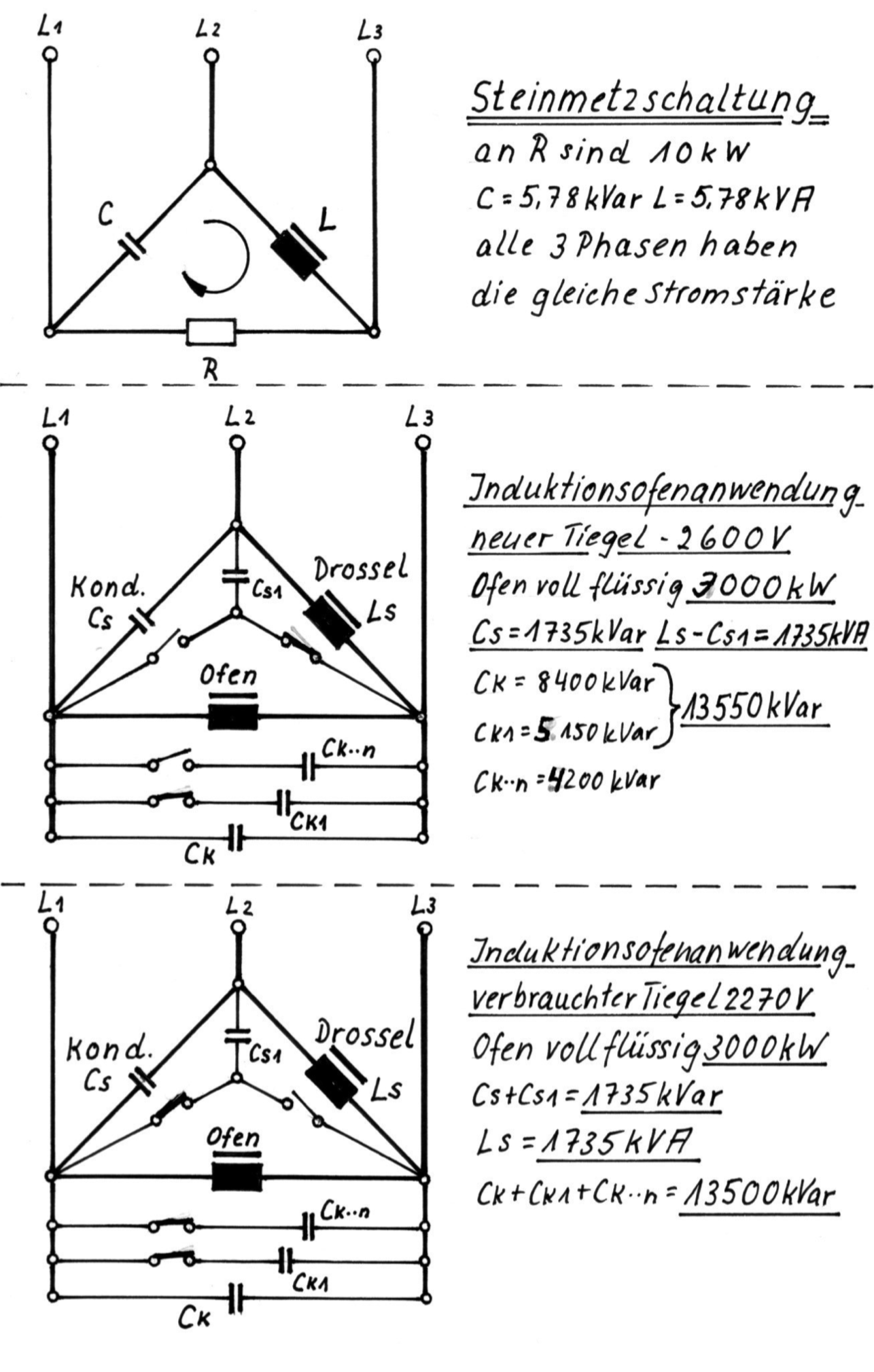
The Steinmetz switching is the balance switching for the operation of 1-phase induction furnaces from 3- phase rotary current networks. In the case of Steinmetz switching, it is assumed that the compensation of the 1-phase furnace is set to 1. By means of balance control, the capacitive part of the balancing is switched in sequence with the inductive part, i.e. the capacity of the balancing condensers equals the output of the choke. By means of corresponding condenser stage switching, condensers are switched in parallel to the choke or the balancing condensers. The level of the balancing performance depends on the output being absorbed by the induction furnace. The ideal figure is the furnace output divided by 1.73. Since a crucible induction furnace is designed so that it can still be operated at nominal load even with approx. 25% washing-out, the transformer steps must be designed in the

same way. The balancing must thus have a sufficient capacity even at correspondingly low furnace voltage. With a 12.5-t furnace with 3,000 kW output at 2,600 V, the voltage steps for the same output would be arranged as follows: 2,600V, 2,490V, 2,380V, 2,270V. The balancing must be designed to cater for this lowest voltage, so that at this voltage, the condenser output still has the required 1,735 kVar and the choke the required 1,735 kVA. At 2,600 V, the balancing condensers thus have 2,275 kVar and the choke 2,275 kVA as the nominal output.

Steinmetz switching

Annealed cast iron

Annealed cast iron (malleable cast iron) is a special type of cast iron that gains its toughness and ductility through controlled heat treatment: cast as hard, brittle white cast iron, then annealed for hours at 900 to 1000 degrees Celsius, which converts the embedded cementite into temper carbon. Used above all where strength and impact resistance are required.

Production process

Annealed cast iron is produced in two clearly defined steps. First, a white cast iron is formed that is extremely hard but brittle. In a second process step, heat treatment takes place — also called “annealing” or “tempering”. Here the material is heated to temperatures between 900 and 1000 degrees Celsius for several hours. During this process, the cementite embedded in the cast iron transforms into temper carbon. This gives annealed cast iron its typical combination of strength and toughness, which makes it particularly valuable in production and processing.

Types of annealed cast iron

A basic distinction is made between black and white annealed cast iron. Black annealed cast iron is produced by annealing under low-oxygen conditions, which converts the cementite into temper carbon more uniformly across the cross-section. It is named after its dark fracture surface and is characterised by particular toughness and ductility. White annealed cast iron, by contrast, is treated in an oxidising atmosphere, which decarburises the edge zone of the component and leaves few carbon deposits at the surface. It offers good weldability and is ideally suited to thin-walled, precision engineering components.

Applications and advantages of annealed cast iron

Thanks to its robust yet ductile properties, annealed cast iron is particularly suited to applications in the automotive industry, mechanical engineering, and fittings and pipe connections in plumbing technology. Its key advantage is that annealed cast iron products combine very high mechanical strength with lasting resistance to vibration and impact loads. This makes them well suited to the requirements for stable, reliable and durable components.

In practice: what the foundry engineer needs annealed cast iron for

For the engineer, annealed cast iron is the material of choice when a component allows the complex geometries typical of cast iron but needs the impact resistance and ductility of steel in service — for example pipe fittings, brackets, or agricultural machinery components. Production requires two clearly separated process steps: first the part is cast as white cast iron with a high proportion of bound carbon (cementite), then it undergoes an annealing treatment of several hours at 900 to 1000 °C, which converts the cementite into temper carbon. In practice, the annealing atmosphere determines the outcome: an oxidising atmosphere produces white annealed cast iron with a decarburised edge zone and good weldability, while a low-oxygen atmosphere produces black annealed cast iron with a more uniform carbon distribution across the cross-section. Wall thickness is a hard limit here: in overly thick-walled components the core no longer solidifies fully white, so graphite forms instead of cementite already during casting, and the later annealing treatment no longer works.

Annealed cast iron grades under DIN EN 1562

DesignationTypeTest piece diameterTensile strength Rm (min.)Elongation A (min.)
EN-GJMW-400-5white annealed cast iron12 mm400 MPa5 %
EN-GJMB-350-10black annealed cast iron (ferritic)12-15 mm350 MPa10 %
EN-GJMB-700-2black annealed cast iron (pearlitic)12-15 mm700 MPa2 %

Values according to DIN EN 1562:2019-06, rounded and given as examples; the standard also covers further intermediate grades. The properties for EN-GJMW-400-5 apply to the 12 mm test piece; at 6 mm the same grade reaches only 300 MPa and 12%.

Frequently asked questions about annealed cast iron

What is annealed cast iron?

Annealed cast iron is a cast iron material that is first cast as a hard, brittle white cast iron and then converted, through an annealing treatment of several hours, into a tough, readily formable microstructure. It combines the castability of cast iron with an impact resistance approaching that of cast steel.

What is white annealed cast iron?

White annealed cast iron (EN-GJMW) is produced by annealing in an oxidising atmosphere. This decarburises the edge zone of the component while temper carbon forms in the core. It can be readily galvanised and welded and is preferred for thin-walled, smaller components.

What is the difference between annealed cast iron and nodular graphite iron?

In nodular graphite iron, the spherical graphite shape forms already during solidification, by inoculating the melt with magnesium. In annealed cast iron, the graphite shape (temper carbon) only forms afterwards, through annealing of cast iron that first solidified white. For large wall thicknesses, nodular graphite iron is more economical, because no additional annealing treatment is needed.

Standard reference

DIN EN 1562:2019-06 sets out grades, designations and minimum properties for annealed cast iron, divided into white (EN-GJMW) and black (EN-GJMB) annealed cast iron.

Related terms