Condensers are used to compensate for the idling output which occurs with an inductive
consumer such as an induction furnace. At 50 Hz, approx. 4.5x the level of the
effective output is needed as the condenser output, if the system is being operated at 250 Hz, approx. 7.5x the level needs to be taken into account, and for systems operating at 500 Hz, the figure is approx. 11x the effective output.
500 Hz – 1,000 kW – 11,000 kVar
250 Hz – 1,000 kW – 7,500 kVar
50 Hz – 1,000 kW – 4,500 kVar
Mains frequency condensers are as a rule air-cooled, while medium-frequency
condensers from approx. 100 Hz are produced as water-cooled units.
A compound alloy consists of at least three components, that is, the base metal plus at least two alloying elements. For comparison: a binary alloy has two components, and a ternary alloy has three.
Cold start is the starting of a crucible following a shut-down. In an NF furnace, starter
blocks are required reaching up to 2/3 of the coil height. These blocks are heated inductively and then settle together. At this point, small quantities of scrap
can be recharged. After reaching the 2/3 filling level, larger quantities of scrap
can be added (5% of the total capacity) and melted. The furnace is brought up to
the maximum filling level at approx. 70% of nominal performance. The melt
should now be brought up to about 100 K below the normal tapping temperature, and maintained at this temperature for 1 hour. The furnace is then brought
up to tapping temperature and the 1st tapping carried out.
Coil jacket is the term for the outer protective cladding of induction furnace coils, consisting of flexible ceramic-organic panels of glass fibre materials. This serves to protect the coil against metallic dusts and spray iron during operation. For safety
reasons, no materials or paint coatings may be used that are impermeable to
moisture. These would then act as a damp course, which can lead to winding
shorts with leakage of water out of the coil. If this water penetrates into the area
of the smelt, this can easily cause water vapour explosions, which usually result
in the uncontrolled ejection of melt from the furnace and the breakthrough of
molten mass through the coil. This can also lead to serious injury to personnel.
Coil repair in the installed condition is only possible in the case of a few furnace manufacturers. This must be an open cage construction, in which the iron piles can if necessary be detached from the outside and moved to the side. The coil jacket is
then cut open at the damaged point of the coil. The coil can then be exposed from
the inside by removing the coil plastering or smooth coil coating. The damaged
intermediate layer insulation is removed, and the defective coil copper cleaned
and repaired. After the water pressure test, the intermediate layer insulation is
installed, the coil copper painted and the repair spot dried with hot air for
approx. 15 min.[1] The plastering can then be applied again. Before lining the crucible, the repair spot should be allowed to dry for 4 to 12 hours, depending on
the thickness and density of the coil plastering.[1] The coil jacket is glued back on
again from outside, and the cut areas sealed off with glass fibre material. The
iron pile or piles are replaced in position and attached using the press-screws.
References
Herbert H. Netzel: Induktionsofenhandbuch. 3rd edition, Eigenverlag IES, Witten 2003, pp. 183–184.
Cogemikanit is a trade name for a plate coating material, which is used in induction furnace construction as an electrical insulation and separating agent on the crucible between the wear crucible and the coil plastering. Plate thicknesses of 0.5 to 2.5 mm can be treated. Above 2.5 mm, the plates are no longer mobile enough, and their application possibilities are therefore limited. There are thicknesses of 0.4; 0.5; 0.6; 0.8; and 1.0 mm on rolls with a width of 1,000 mm and lengths of 10 to 25 m, depending on the thickness.
A special version is Cogemikanit with internal “fly screening” and an outer layer
of 0.5 mm micanite for the connection of monitoring systems in crucible furnaces.
Iron piles are insulated against the coil outer jacket with 2 mm of Isoplan and
depending on the operating voltage, with 2x 0.5 to 6x 0.5 mm of Cogemikanit at
3,000 volts.
Circuit is a designation for cast recycling materials from the foundry’s own production.
These may be sprues, risers or connectors. In some businesses, rejects are incorrectly counted as part of the circuit, although this is not advisable from a commercial standpoint. In the case of rejects, a distinction must be made between
direct casting rejects from the mould, casting faults following cleaning, faults following mechanical processing and faults following annealing. With the aid of
suitable measures, these individual faults can be minimised, and costs reduced
significantly.
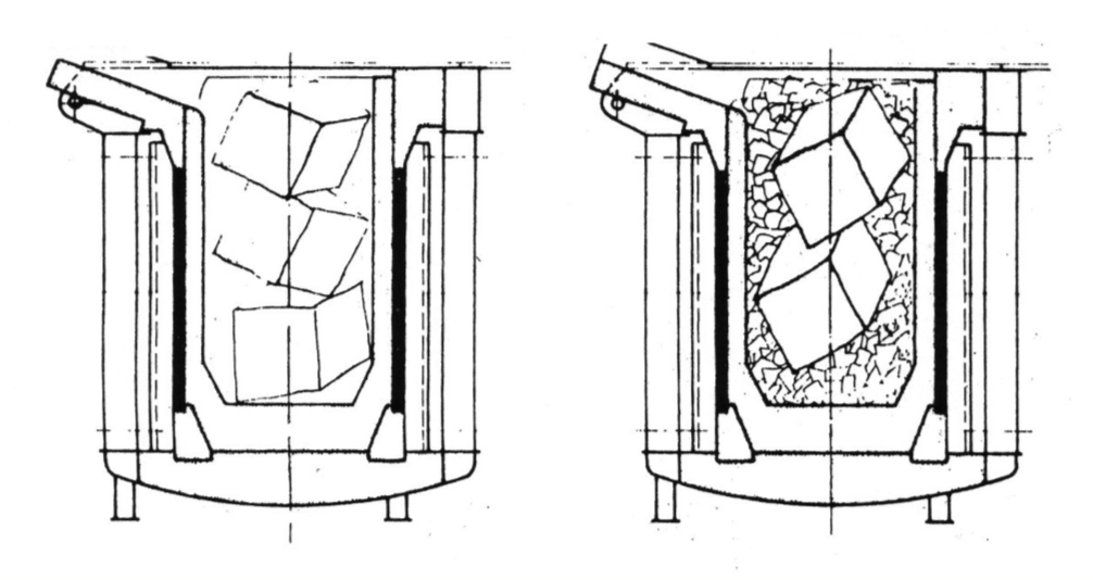
Chip melting is associated with various difficulties due to the relatively low weight of the chips. Most customers have developed their own processes, which in combination with the available equipment are used quite successfully. The use of “chip briquettes” has not proven popular. The specific density or filling weight is too low for them to be immersed properly in the melt. The briquettes fall apart shortly after contact with the melt, and the chips spread out over the surface of the bath. In the case of channel melting furnaces, some success has been achieved with the use of mechanic stirring systems. Brass melting furnaces with channel inductors are for example equipped with concrete blocks, which cover approx. 80% of the surface, and which are installed by cranes for lowering onto the charged scrap. In crucible induction furnaces, the filling level in the coil should generally be 40%. With dry chips and high specific outputs, the chips can be charged in up to the upper edge of the coil.
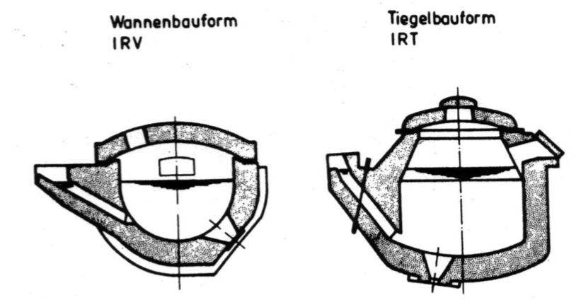
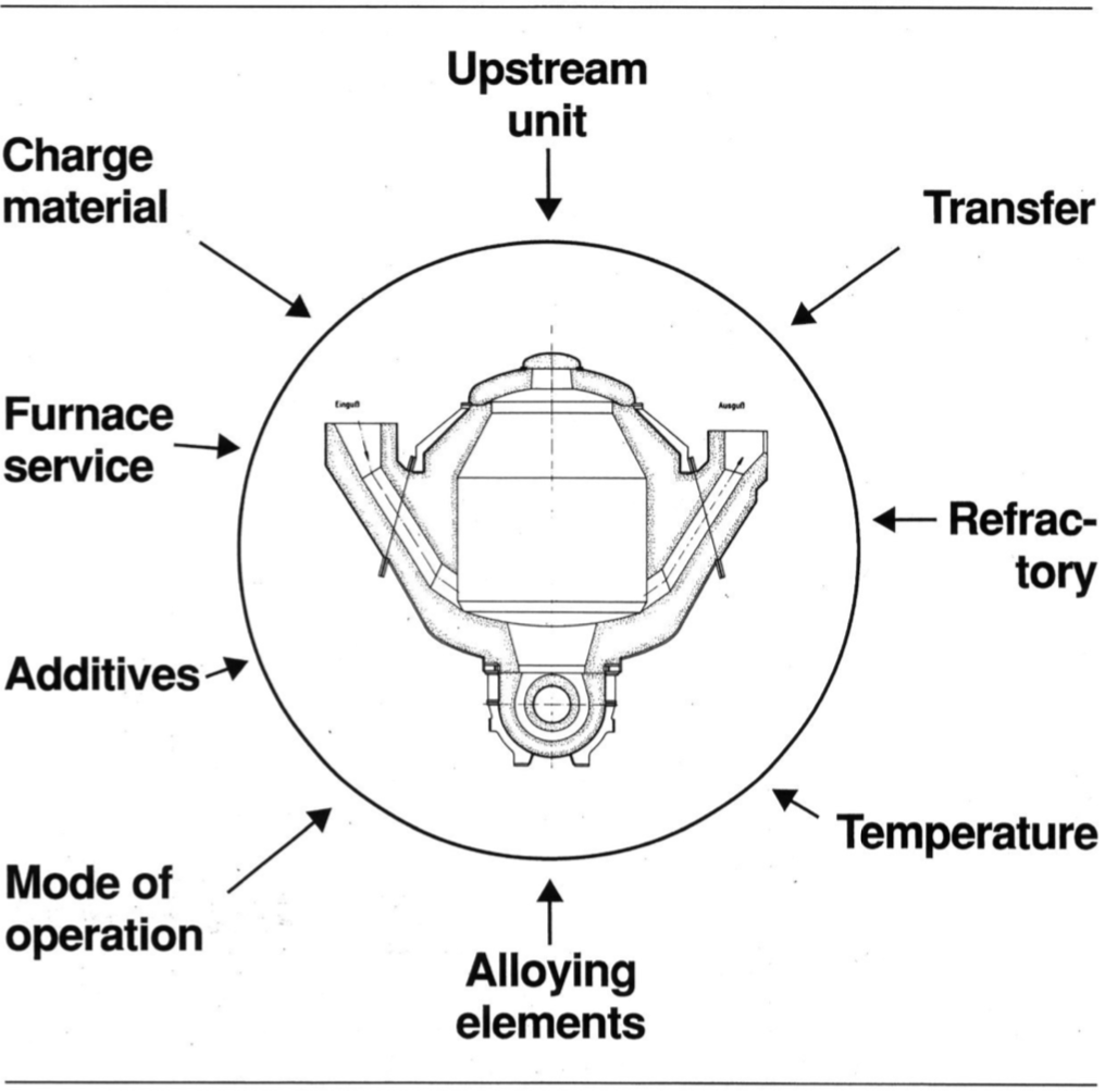
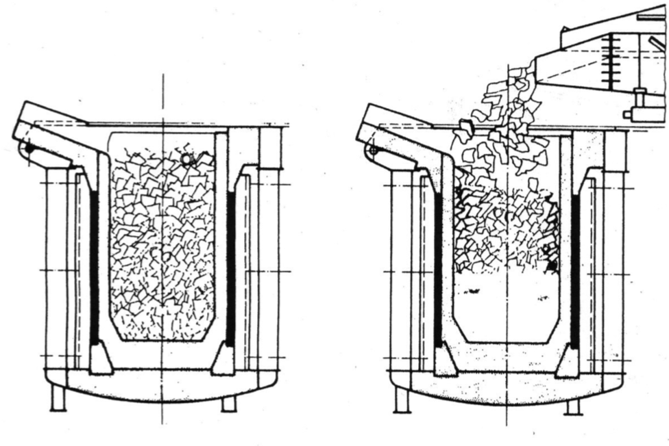
Design of vat-shaped (IRV) and crucible-shaped (IRT) cannel-type furnacesCross-section through the vessel of a tub-shaped (left) and crucible-shaped channel-type furnace tub shape (IRV) – crucible shape (IRT)Influences on the channel furnaceCharging of medium-frequency melting furnaces in charging/melting mode with large sized and bulky charge materialCharging of medium-frequency melting furnaces in charging/melting mode with normal sized and small charge material
In mains frequency furnaces, melting usually continues until a smooth bath surface appears before recharging. In foundries with medium-frequency furnaces, recharging usually takes place earlier. With this procedure, melting can be continued up to the upper edge of the furnace coil, before bringing the furnace up to the maximum melt level using compact scrap or pigs. With modified outputs and frequencies (240 kW/t for low frequency, 540 kW/t at 250 Hz and 760 kW/t at 500 Hz), continually charged chips charged in on top of the molten bath can be melted from approx. 30 to 70% of the filling level. For brass or red cast, and using this process at approx. 330 kWh/t and 960 kW furnace output with mains frequency in a 4-t furnace, approx. 1.6 t of chips can be melted in approx. 33 min. An important factor here is that the chips must be fed evenly over the centre of the bath at a rate of approx. 45 to 50 kg/min.
Trials with an 18-t brass-furnace at 3,500 kW have shown that this method of melting works very well up to a rate of approx. 175 kg/min. From approx. 200 kg/min of continuous charging, a ring formed around the crucible wall which could no longer be melted, but had to be brought into the melt manually.
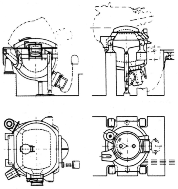
Channel furnace is the term for an induction furnace that is operated with 1 to 4 channel inductors. Channel furnaces are generally used as holding or storage furnaces. Due to their high efficiency, channel furnaces are also used for the melting of non-ferrous metals and zinc. This principle and design have not however proven popular for grey cast iron. In non-ferrous metal foundries, the double-chamber channel furnace has come into common use. This consists essentially of a channel inductor with 2 flanges, to which are flanged an inlet chamber and a casting chamber. These furnaces have only a low output, which is not suitable for the melting of solid charge materials. For aluminium, higher-performance furnaces are available, which can also melt solid pigs.